
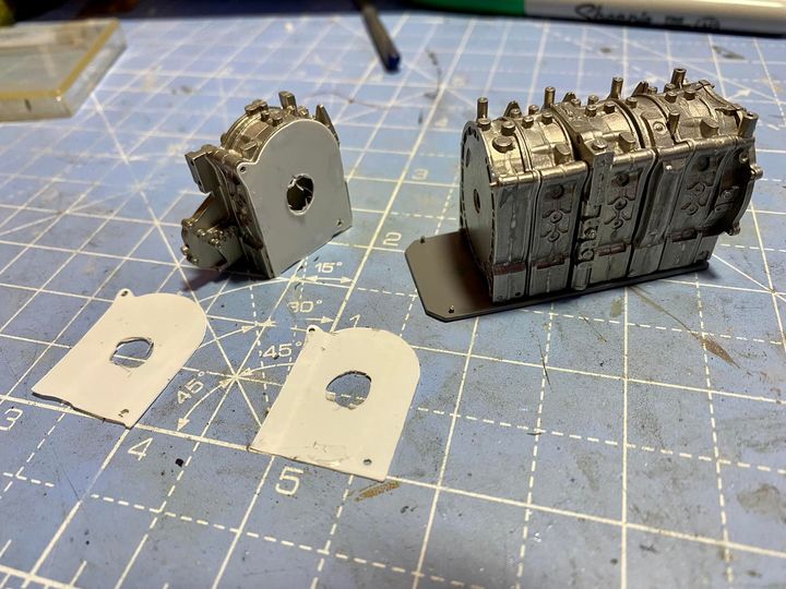
A very long time ago a fellow 787 builder (Jason Rubens – you can find his blog in the links page) pointed out that he had discovered the assembled engine was too short to fit the mounts on the plates it fits to. It can’t just be lengthened at one point, as it throws out the fit of a lot of other parts. His idea was to make brass shims to put between each component, which I’ve adapted to make out of plastic sheet. I scanned one of the rotor housings, and drew a cut for my Cameo Silhouette plotter cutter. I calculated eight would be needed, but after test fitting only six made the necessary difference to make the holes and pegs meet properly. It’s only mounted with PVA glue so far, so I can reverse the process if I need to. Next up is to make sure all the ancilleries still fit properly before making it permanent. Thanks Jason!
3rd July 2022 – Pretty much all of my modelling time this week has been getting paint on the engine. There are getting on for 40 parts in the pictures below, all in white metal. I’m so pleased I decided to splash out on a magnetic tumbler and it made cleaning and finishing them all so much easier. The basic parts were primed with an etch primer, which I can’t recommend highly enough for metal parts. They were then finished in Tamiya LP-1 gloss black. Thinned with Mr. Color Levelling Thinner it gives a great finish, which can be enhanced by letting it dry for a short time and hitting it again with the same paint but thinned further. Super glossy!

Luckily I have a whole shelf of Alclad II metallic lacquers so there was plenty of choice for representing the various materials and finishes. When I first started building this I thought that 1/12 scale detail would have natural highlights and shadows, but standard techniques of a basic wash of some thinned black oil paint and little dry brushing really do enhance the finish.
I don’t believe in adding or painting detail that can’t be seen. It’s time that could be spent on other parts of the process, but I did get accidentally sucked in to painting some hidden detail on the clutch housing and bell spring. I was really pleased with the finish, and quite dismayed that it all disappeared from view when I offered up the gear box for a test fit!

In the final picture below you can see the holes for the exhaust (bottom row) and the charge intake (top row). The beginnings of the wiring for the sparking plugs are on the carbon fibre deck, and the pulley like actuators for the throttle bodies are also visible.

